USB4 is the latest generation of the USB standard, built on the USB Type-C connector and capable of tunneling USB 3.2, DisplayPort, and PCIe data over a single cable. To understand how a USB4 docking station, hub, or external SSD enclosure actually moves data, it helps to look at how the whole USB4 system is structured. Below we break down the USB4 system structure — including routers, adapters, tunneling, retimers, and links — in plain terms.
The computer host, hub (or docking station) and external devices together form a USB4 system. That is, all the interdependent parts of USB4 are combined into a whole called USB4 system. The USB4 system structure (English name USB4 Fabric) includes one or more combinations of USB hosts, USB4 hubs and USB4 external devices.
USB4 system structure
The transmission of USB 3.2 data, DisplayPort data and PCIe data between USB4 hosts, USB4 hubs and USB4 external devices can abstract the following model.
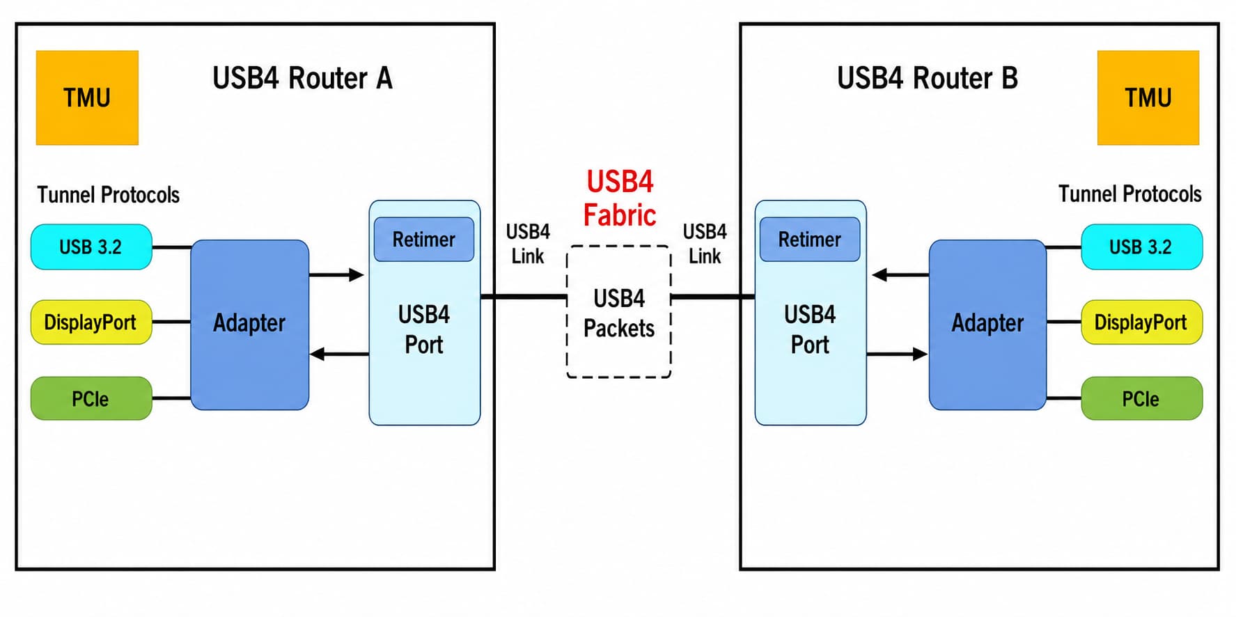
1. Tunnel protocol
The way in which data from different protocols will be integrated in the future is called a tunnel protocol. What is transmitted is tunnel data. USB4 tunnel refers to the path for transmitting USB4 tunnel data. USB4 tunnel data refers to a data form that integrates USB 3.2 data, DisplayPort data and PCIe data. There are also commonly mentioned USB 3.2 tunnels, DisplayPort tunnels and PCIe tunnels respectively referring to the respective transmission paths of USB 3.2 data, DisplayPort data and PCIe data.
2. Router
The router mentioned in this article is a different concept from the router that is often used to separate wireless networks in our daily life. The router mentioned in this article refers to a basic module of the USB4 system structure. It has two functions:
Choose the best transmission route between two points
Transmitting USB4 data packets through the USB4 system structure
Routers are divided into two types: host routers and device routers. For example, a laptop with USB4 function must have a host router, a hub that extends a USB4 interface to multiple USB4 interfaces, a DisplayPort monitor that receives signal video, and a solid-state drive and a mobile hard drive. Such external devices must have device routers.
USB 3.2, DisplayPort and PCIe are equivalent to 3 passengers, and the router is equivalent to a taxi driver. After determining the starting point and destination, it chooses the best driving route to take the passengers to the designated location.
3. Adapter
Adapters provide interfaces for connections between routers and external entities. Each router contains up to 64 adapters. There are three types of adapters: protocol adapters, channel adapters and control adapters.
3.1. Protocol adapter
Use a protocol adapter to convert between supported native protocols and USB4 tunneling.
There are four types of protocol adapters: USB3 adapter, DisplayPort (DP) adapter, PCIe adapter and Host Interface (HI) adapter. The function of USB3 adapter, DisplayPort adapter and PCIe adapter is to convert USB 3.2 data, DisplayPort data and PCIe data into USB4 tunnel data, or to convert USB4 tunnel data into USB 3.2 data, DisplayPort data and PCIe data respectively.
3.2. Channel adapter
Channel adapters provide interfaces for channels. There is one channel adapter for each channel of the USB4 port.
3.3. Control adapter
The router contains a control adapter. The control adapter is an abstract concept and has no physical entity. The control adapter is the end consumer of control packets directed to the router. The control adapter also generates control packets, which are sent to the connection manager.
4. Time management unit
Time Management Unit (TMU, Time Management Unit) is the functional module of each router. The router allocates and synchronizes time throughout the entire USB4 system structure through its time management unit. There is a certain time delay in data transmission, and the time for data transmission needs to be allocated and synchronized timing is also required.
The synchronization management unit is to ensure that data transmission between different routers has a unified timing method. Just like in life, when two people get together, they all agree on the time according to Beijing time. If one party is far away from the meeting point and one party is close to the meeting point, then the closer party can start at a later time.
5. Retimer
A USB4 product can contain up to two onboard retimers per USB4 port. The function of the retimer is to reorganize the signal of the previous stage and pass it to the next stage. It has the function of recovering data and reduces the possibility of data transmission errors.
6. Connection Manager
A connection manager is a software entity responsible for enumerating, configuring, and managing routers. The connection manager performs tasks such as path setup and teardown, hot plugging and unplugging, and bandwidth management. The connection manager is part of the USB4 host system.
7. USB4 link
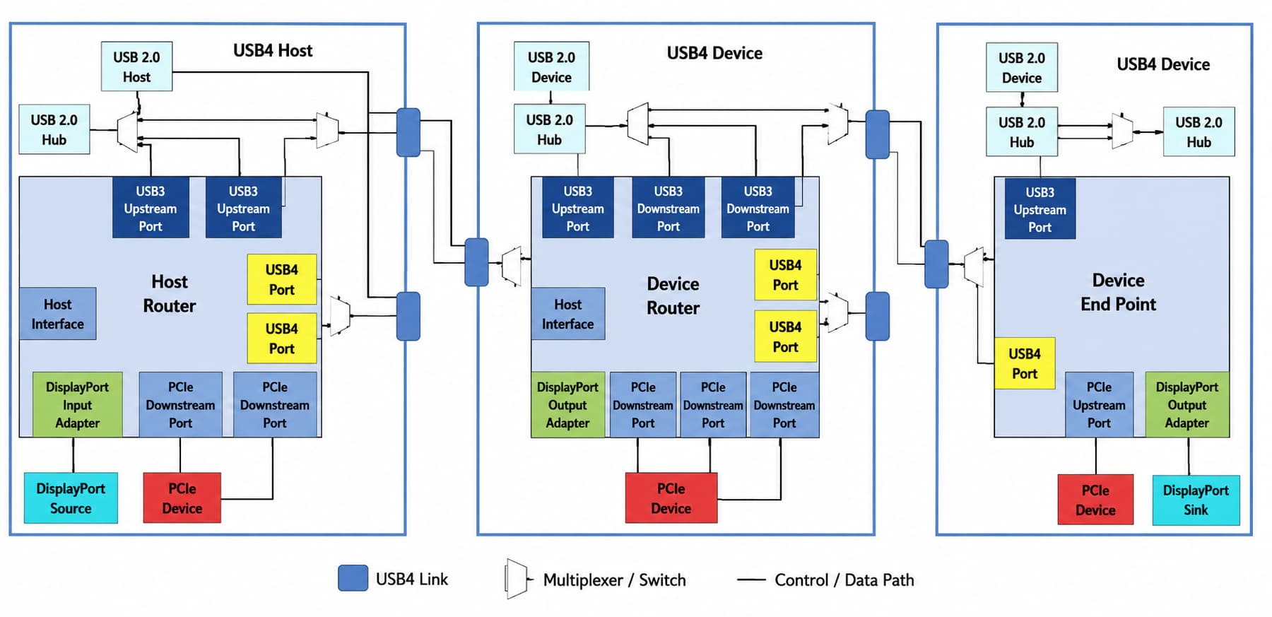
A link refers to a real line from one point to another point, called a physical line. There are no other nodes in between. A USB4 link refers to the connection between USB4 ports of interconnected routers. The figure below illustrates the connection between a USB4 host and a USB4 device.
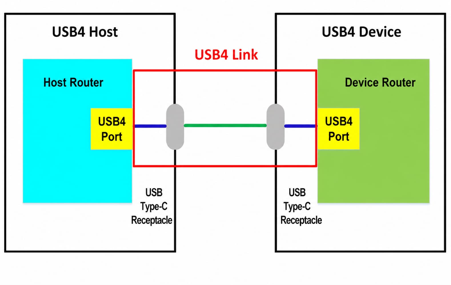
It can be seen intui-tively that the USB4 link is the part circled by the red box. That is, the blue connection part of the USB4 port of the USB4 host and the USB4 device is connected to the USB Type-C female socket, and the green connection part is connected to the two USB Type-C female sockets. Together they form a USB4 link. Among them, the green connection represents a cable with USB Type-C male connectors on both ends. The blue connection represents the line on the circuit board between the USB4 port of the USB4 host and USB4 device to the USB Type-C female socket.
8. From system structure to everyday connections
Understanding the USB4 system structure isn't just theo-ry — it explains why a USB4 setup behaves the way it does in daily use. The router chooses the transmission route, the retimer cleans up the signal to reduce data errors, and the link is the actual physical cable-and-port path that carries everything. Because so much depends on that physical link, the cable and the port are also the most common points where real-world problems appear.
Even with USB4's error-reducing architecture, a worn cable, a loose connector, or a faulty port can still interrupt power delivery or data transmission. If your device isn't being detected or a connection keeps dropping, the issue is often at the link layer rather than the protocol itself. In that case, our step-by-step guide to troubleshooting a USB port that is not working walks through port testing, cable inspection, device cross-testing, and hub power checks to help you isolate the cause.
Frequently Asked Questions
Q1: What is the USB4 system structure?
A1: The USB4 system structure (USB4 Fabric) is the combined architecture of one or more USB hosts, USB4 hubs, and USB4 external devices, along with the routers, adapters, tunnels, retimers, and links that move data between them.
Q2: What does a router do in a USB4 system?
A2: A USB4 router is a core building block that selects the best transmission route between two points and forwards USB4 data packets through the system. Hosts use host routers; hubs and external devices use device routers.
Q3: What is USB4 tunneling?
A3: Tunneling is how USB4 carries multiple protocols over one connection. A USB4 tunnel integrates USB 3.2, DisplayPort, and PCIe data into a unified data form, with protocol adapters converting between each native protocol and USB4 tunnel data.
Q4: What is a USB4 link?
A4: A USB4 link is the physical connection between the USB4 ports of two interconnected routers — including the cable with Type-C connectors and the on-board traces from each USB4 port to its Type-C socket.
Q5: Why is my USB4 device not working even though the structure supports it?
A5: Most connection failures occur at the physical link — the cable or port — rather than the protocol layer. Testing a different port, swapping the cable, and checking hub power usually isolates the problem.