IDE interface
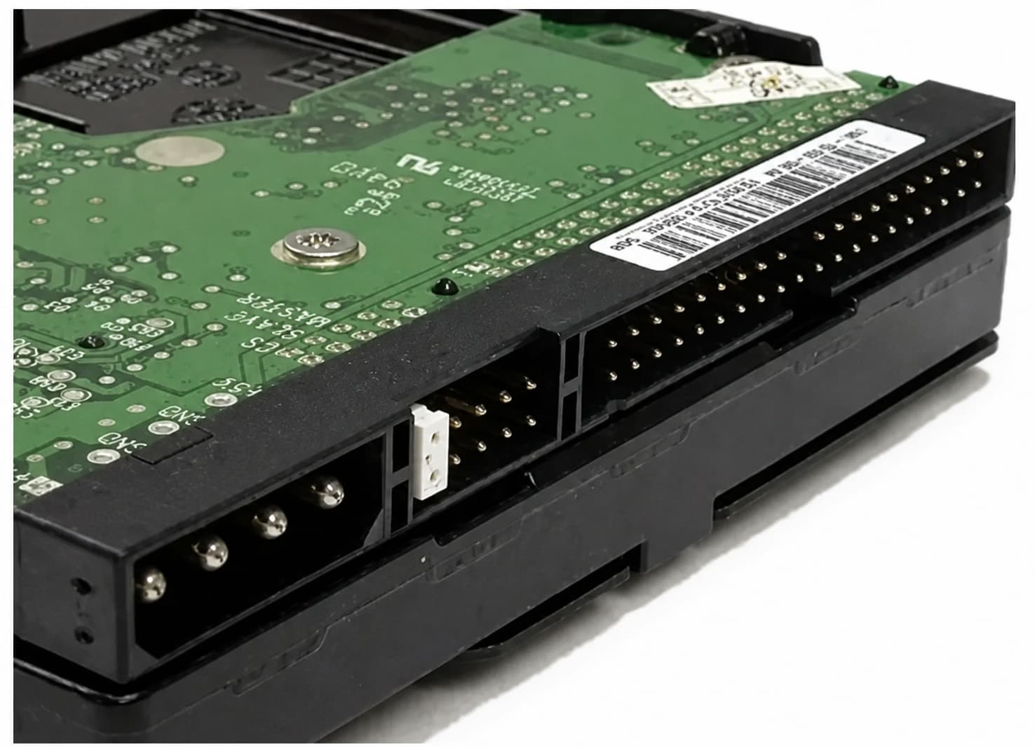
IDE is short for "Integrated Drive Electronics". In PC storage discussions, the term commonly refers to PATA, an older standard electrical interface between the hard disk and the computer motherboard.
One of the main advantages of the IDE design was that the hard disk controller was integrated with the hard disk body, which simplified system design and the manufacture and installation of the hard disk. The IDE interface supports parallel data transmission. Desktop PATA drives use 40-pin connectors; the familiar 80-wire IDE cable still has 40-pin connectors, but its 80 conductors improve signal integrity for faster Ultra DMA modes. In older PC usage, IDE was often used as shorthand for PATA (Parallel ATA); the ATA family also includes SATA. SATA has replaced the IDE interface as the mainstream PC storage connection.
SATA interface
SATA is short for Serial ATA, which has several advantages over PATA, including higher interface rates and optional hot plugging when the platform supports it. Its point-to-point link connects one drive to one host port. Official rate names are 1.5, 3, and 6 Gb/s—not “SATA I/II/III.” Hot-plug support depends on the controller, firmware or BIOS, operating system, and bay hardware. In addition, SATA cables are thinner and simpler, making it easier for users to install them on the computer, and are also conducive to air circulation in the computer case.

SATA vs IDE: how do these hard disks differ?
SATA and IDE differ in topology, interface rate, cabling, and compatibility. The comparison separates interface limits from actual drive performance—a distinction that matters in system specifications and legacy migrations.
| Comparison | IDE / PATA | SATA |
|---|---|---|
| Data path | Parallel, shared channel | Serial, point-to-point link |
| Top named rate | Ultra ATA/133: 133 MB/s | SATA 6 Gb/s: 600 MB/s interface rate |
| Data cable | 40-pin connectors; 40 or 80 conductors; 18 in max | 7-pin data connector; up to 1 m |
| Devices | Up to two per cable; master/slave or cable select | One drive per cable and host port |
| Typical power plug | 4-pin peripheral connector on 3.5-inch drives | 15-pin SATA power connector |
1. Interface type and data transmission method
IDE interface: IDE is the abbreviation of Integrated Drive Electronics; in this article, it means PATA, which uses parallel data transmission. Parallel transmission means that data is transmitted on multiple lines at the same time, but at high frequencies this method faces tighter timing limits. One channel can host two devices; jumpers or cable select identify master/device 0 and slave/device 1.
SATA interface: SATA (Serial ATA) uses serial data transmission. Unlike parallel transmission, serial transmission sends data over separate differential transmit and receive pairs in a 7-pin cable; it does not literally use only one line. This point-to-point method gives each device its own port, eliminates the master/slave relationship, reduces parallel timing constraints, and supports higher interface speeds.
2. Transmission rate
IDE interface: The transmission rate of hard disks with IDE interface is relatively low. According to the specification, its maximum transmission rate can reach 133 MB/s with Ultra ATA/133. That is an interface ceiling, not guaranteed sustained disk throughput.
SATA interface: The maximum rate of the SATA interface is much higher. For example, the transmission rate of a SATA 6 Gb/s interface can reach 6 Gb/s, which corresponds to 600 MB/s of interface data rate after 8b/10b encoding—not 750 MB/s. A mechanical hard drive may sustain far less, so interface rate and file-transfer speed are not the same number.
3. Cables and connections
IDE interface: Hard disks with IDE interface are connected using a 40-pin connector and either a 40- or 80-conductor flat cable. The length of such cables is limited: the standard internal maximum is 18 inches (457 mm). Up to two devices can share a cable with jumpers or cable select.
SATA interface: Hard disks with SATA interface are connected using slender 7-pin data cables and a separate 15-pin power connection. These data cables can be up to 1 metre long and are easier to install. Each cable links one drive to one host port, not multiple devices.
4. Function and compatibility
IDE interface: Hard disks with IDE interface usually integrate the disk body with the controller, which simplified system design and installation. SATA later replaced IDE in most current systems. PATA remains useful when legacy hardware requires it; check the jumper, power connector, BIOS support, and capacity limits.
SATA interface: SATA offers higher interface rates, a longer internal cable limit, and point-to-point connections. It is not natively backward compatible with IDE devices. An IDE-to-SATA connection needs an active converter whose direction matches the job. Hot swap works only when the controller mode, firmware, operating system, power sequencing, and bay all support it.
- Confirm the data and power connectors; 2.5-inch and 3.5-inch PATA hardware can differ.
- Check bridge direction: SATA-to-IDE and IDE-to-SATA are different jobs.
- Check the host's BIOS, boot, capacity, and file-system limits.
- Image valuable media first; test the bridge with non-critical data.
5. Other advantages
SATA interface: Practical advantages include thinner cables, independent ports, and no master/slave setup. Serial transmission does not prove that power consumption is much lower than that of IDE interface hard disks. Total power depends on the specific drive; compare its datasheet when power or thermal design matters.
For a current system, SATA is generally the better fit for interface rate, cabling, compatibility, and parts availability. Keep IDE when a legacy host or recovery task requires it. Before ordering an adapter, check both connectors, conversion direction, drive power, host support, and boot requirements. PURPLELEC can help review these conditions before a legacy-storage connection solution is specified.
Frequently asked questions
Can SATA and IDE use a passive cable?
No. Different signalling and protocols require an active, direction-correct bridge.
Can every SATA drive be hot-plugged?
No. The controller, firmware, operating system, power, and bay must support it.
Does SATA 6 Gb/s mean 600 MB/s file copies?
No. That is the interface data rate; sustained drive speed may be much lower.
How do I identify an 80-conductor IDE cable?
It still has 40-pin connectors, but finer wires and usually blue, grey, and black plugs.